Enter product details (such as color, size, materials etc.) and other specific requirements to receive an accurate quote.
leave a message
If you are interested in our products and want to know more details,please leave a message here,we will reply you as soon as we can.
submit
other
Home Blogs

Blog

Blog

  • What Technical Parameters Does a Kaolin Vertical Roller Mill Have?
    What Technical Parameters Does a Kaolin Vertical Roller Mill Have?
    Jul 17, 2026
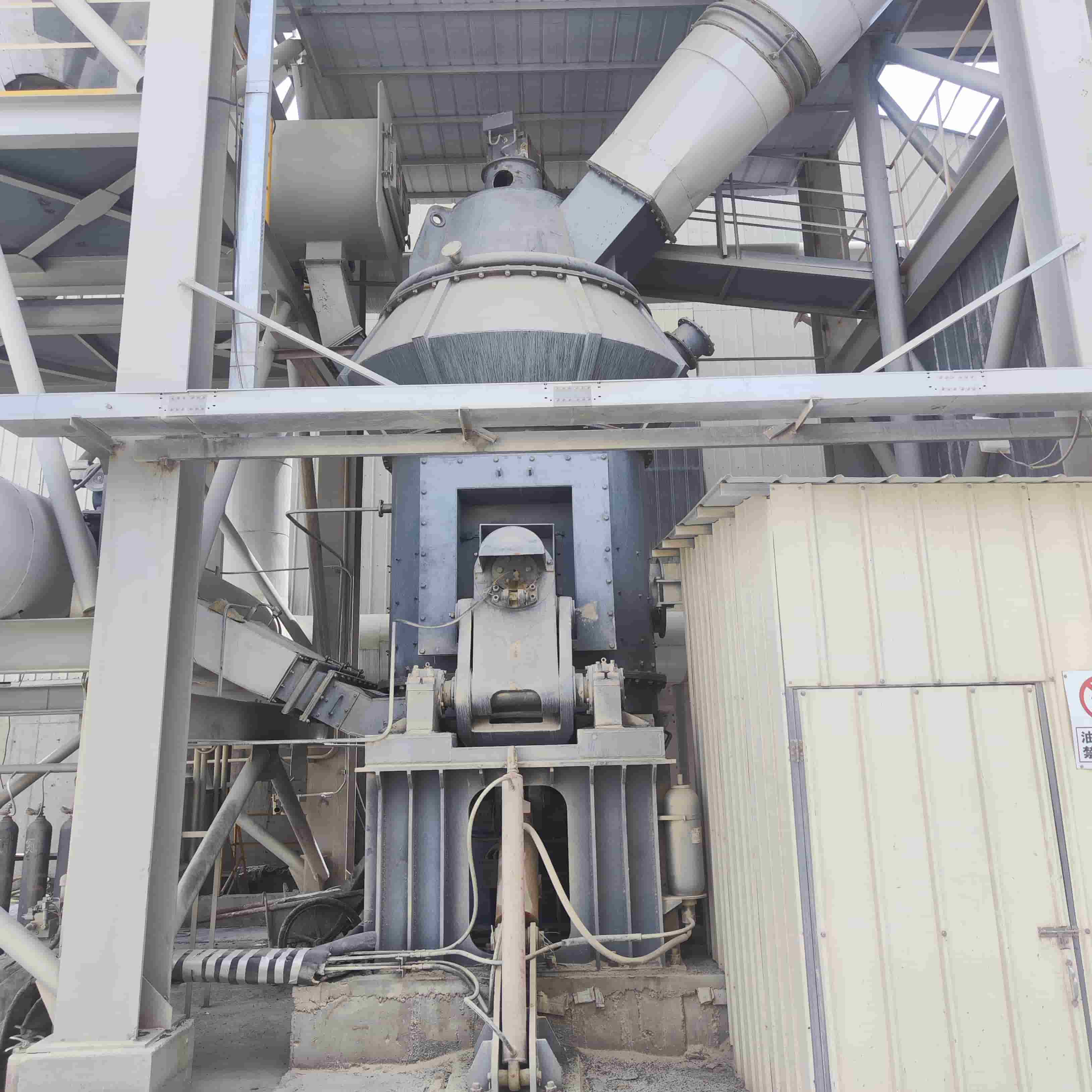
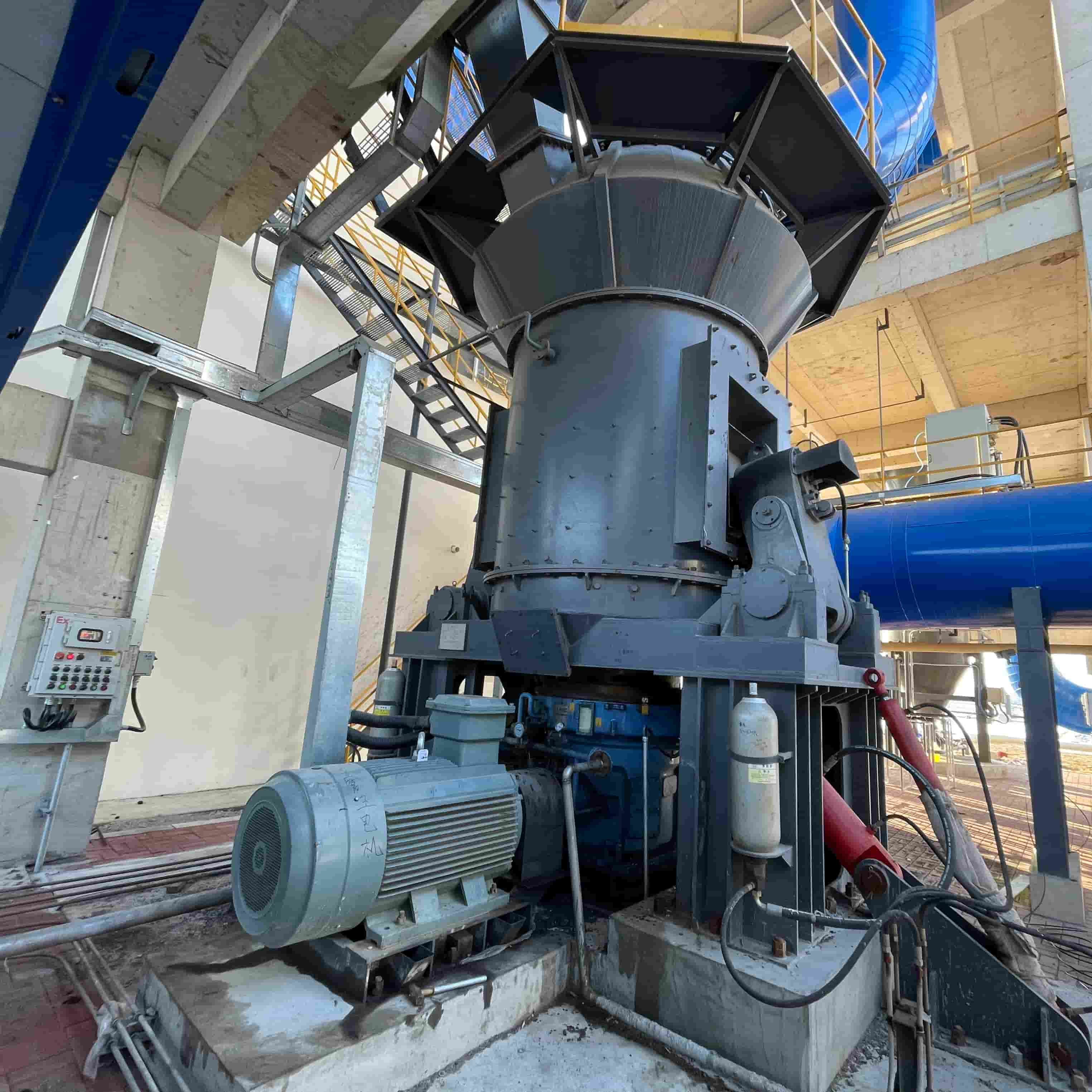
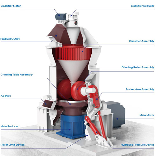
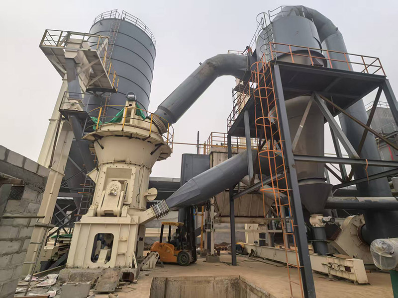
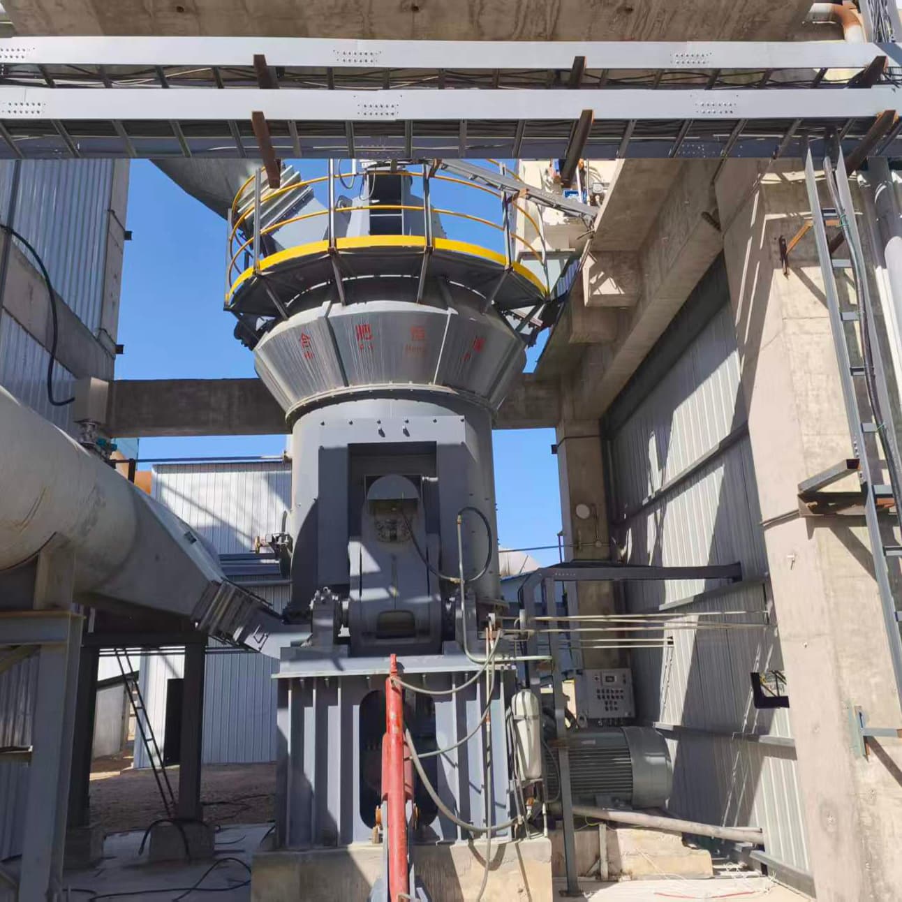
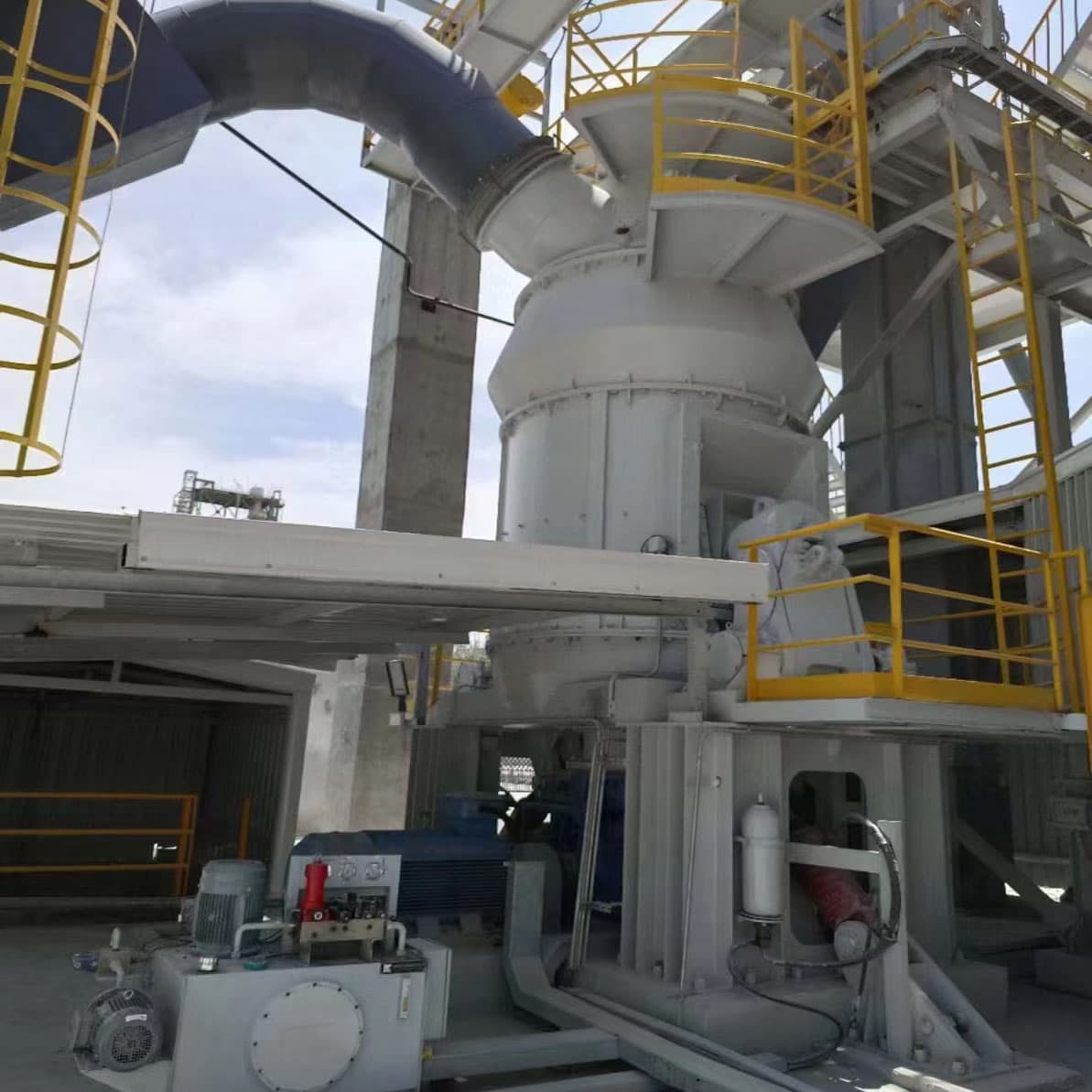
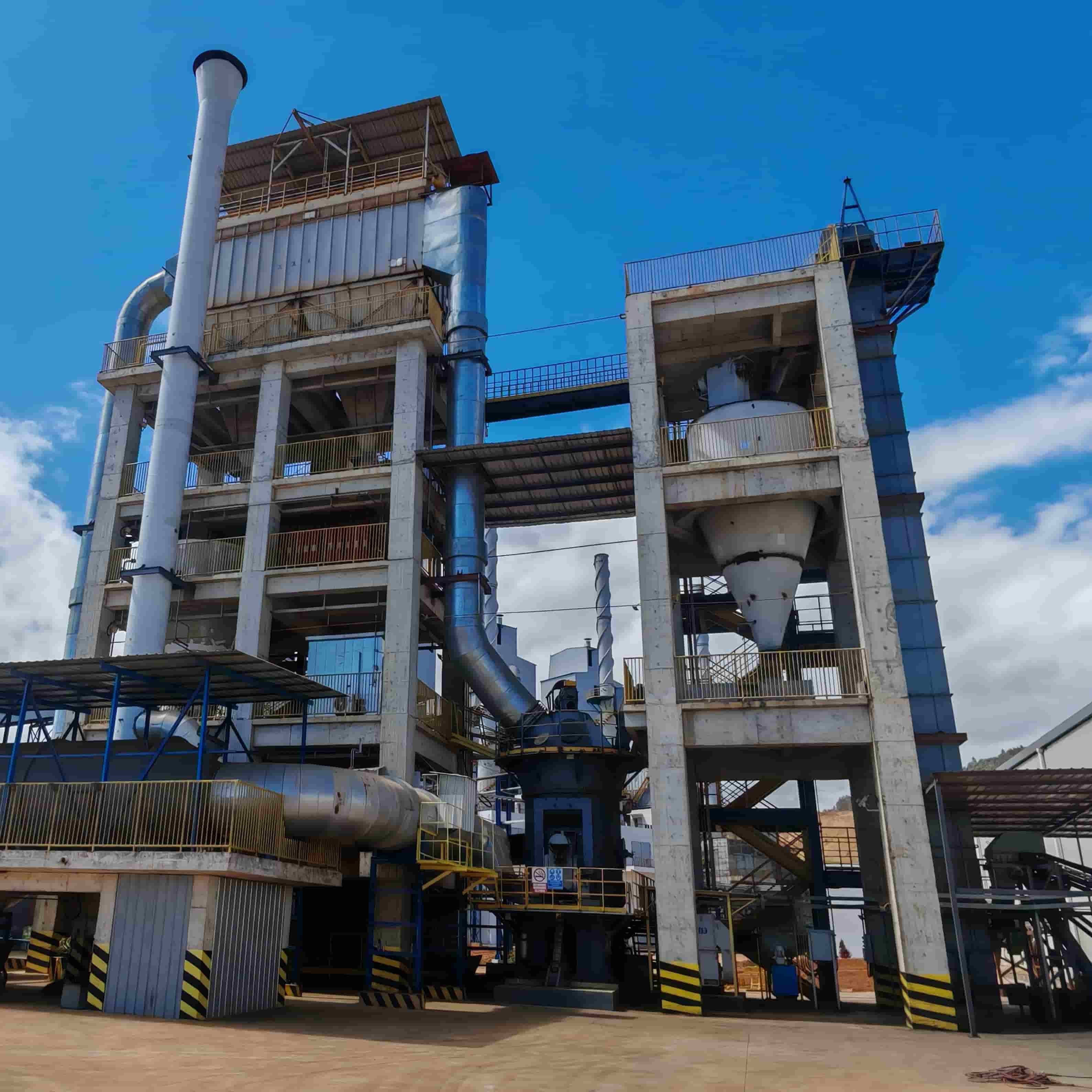
    Overall Appearance Drawing of Kaolin Vertical Roller Mill   Kaolin is one of the most widely used industrial minerals, and vertical roller mills (VRM) have become core processing equipment for kaolin. Integrating grinding, classification, drying and conveying in a single unit, they stand as the top choice for kaolin manufacturers. So what specific technical parameters does a vertical roller mill for kaolin processing feature, and why do these parameters matter? This article breaks down all key specifications in detail to clarify the critical factors for your equipment selection.   Why Should You Pay Attention to Technical Parameters for Kaolin Grinding? The value of kaolin directly depends on its particle size, whiteness and purity. The grinding process must achieve precise fineness, generally ranging from 325 mesh (45 μm) to 2500 mesh (5 μm), to meet the standards of downstream industries such as paper coatings, ceramics, paints, plastics and cosmetics. Vertical roller mills can produce ultra-fine powder with uniform particles and narrow size distribution, making them the preferred grinding technology.   Key Technical Parameters of Kaolin Vertical Roller Mill 1. Grinding Disc Grinding The millstone diameter directly determines the mill’s production capacity. A larger diameter allows higher material throughput and output. Model Series Grinding Disc Grinding (mm) Capacity(t/h) HVM1400 1400mm 3–14 (Depends on target fineness) HVM1600 1600mm 5-17 HVM1700 1700mm 6-19 Data of HVM series based on calcite test; output varies with target fineness. For large-scale production demands, the HVM2400 model features a 2400 mm millstone diameter with a capacity up to 40 t/h, fully meeting the requirements of mass industrial production.     2. Number of Grinding Rollers Grinding rollers exert compressive force on the material bed atop the rotating millstone. The quantity of grinding rollers directly impacts grinding efficiency and operational stability. HVM Series: Equipped with 2 to 3 grinding rollers as standard.   More rollers generally deliver stronger grinding pressure and higher output of fine powder, yet the exact number is determined by the overall mill design.     3. Fineness Range of Finished Powder Fineness is the most critical indicator for kaolin grinding. Modern vertical roller mills equipped with high-efficiency dynamic classifiers enable precise particle size control, with adjustable fineness without machine shutdown.   Typical fineness range: 300–3000 mesh (47–5 μm). Ultra-fine grinding capacity: Fitted with a secondary classification system, certain mill models can reach a fineness of 3 μm (D97). Precise classification: The integrated classifier guarantees narrow particle size distribution, which is essential for high-standard applications such as paper coatings.     4. Feed Particle Size and Moisture Handling Capacity These two parameters define the basic raw material requirements for the mill. Maximum feed particle size: For the HVM series, the standard feed size is less than 10 mm or up to 20 mm. Certain models fitted with a pre-crushing system are capable of processing materials with a particle size no greater than 50 mm.   Raw material moisture: Most vertical mills are equipped with a hot air system, enabling them to process feedstock with a moisture content of 3% to 5% without external drying equipment. Special customized designs can handle raw materials with moisture levels as high as 15% in a single pass. This built-in drying performance constitutes a prominent advantage. It eliminates the need for standalone drying units and streamlines the overall production process.       5. Metal Wear and Product Purity Kaolin purity is critical, especially for high-end application scenarios. HVM Vertical mills are engineered to minimize metallic contamination generated during the grinding process.   Metal wear rate: As low as 5–10 grams per ton of processed material. Wear-resistant materials: The grinding rollers and grinding table liners are fabricated from special wear-resistant alloys to extend service life and cut down contamination. Reduced wear brings higher product purity alongside lower maintenance costs, serving as a core selling point for customers targeting high-end markets.       6. Energy Efficiency Power consumption accounts for a major share of operational costs. Vertical mills deliver remarkable power savings in comparison with conventional ball mills.   Power saving performance: Energy consumption is reduced by 30%–40% versus ball mills. Integrated process merits: Integrating grinding, drying and classification into one unit removes the requirement for multiple standalone machines. The overall plant energy consumption can be lowered by 30%–50% comprehensively.     Whether your target markets are paper coatings or high-performance industrial fillers, selecting a vertical mill with matched parameters is critical to your market competitiveness. If you require accurate recommendations tailored to your specific raw material properties and production capacity targets, please consult the technical team of the equipment manufacturer.     Have any further questions regarding vertical mill model selection? Feel free to get in touch with our technical team for a customized evaluation solution.
  • Pneumatic Conveying Jet Pump: Working Principle, Benefits and Typical Applications
    Pneumatic Conveying Jet Pump: Working Principle, Benefits and Typical Applications
    Nov 03, 2026
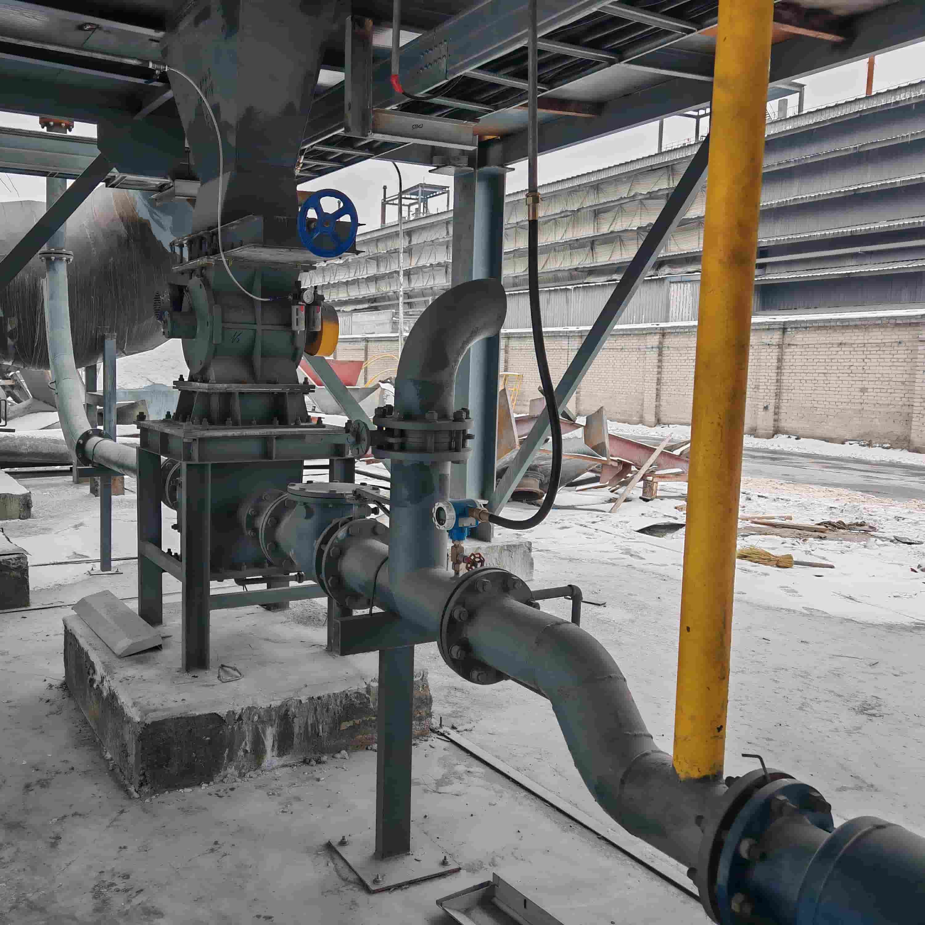
    Pneumatic Conveying Jet Pump: Working Principle, Benefits and Typical Applications A pneumatic conveying jet pump, also known as a pneumatic ejector or jet ejector, is a core dilute-phase powder transfer device powered by compressed air. With no internal moving parts, it reliably conveys fine bulk powders such as graphite powder, gypsum, cement and fly ash in a fully sealed pipeline with minimal maintenance.   What Is a Pneumatic Conveying Jet Pump? The HCPJP® Jet Pump is a low-pressure, dilute phase, continuous positive-pressure conveying device. It typically uses a Roots blower as the conveying power source, with an air supply pressure generally not exceeding 100 kPa. During conveying, the solid-to-gas ratio typically ranges from 5 to 15 kg/kg. How Does a Pneumatic Conveying Jet Pump Work? Material enters the jet pump chamber. When the gas source is ejected at high speed through the nozzle, the resulting high-velocity flow creates a negative pressure inside the chamber, allowing the material within the pump to mix readily with the high-speed gas stream. The mixture is then discharged through the venturi tube, where the kinetic energy of the high-velocity gas flow is converted into static pressure energy, thereby conveying the powdered and granular materials through the conveying pipeline to the destination. Key Advantages of Pneumatic Conveying Jet Pump The entire jet pump body has no moving parts, relying entirely on the Venturi tube structure to achieve jet conveying, thus ensuring long-term, reliable operation. ✅ No moving parts: No jamming, less wear, fewer spare parts replacement, long service life ✅ Fully enclosed, dust-free conveying: Reduces powder leakage and workplace dust hazards ✅ Simple structure & compact layout: Easy to retrofit into existing silo feeding systems ✅ Suitable for abrasive powder: Works well for fly ash, alumina, graphite, lime and gypsum powder ✅ Explosion-safe design: Compatible with ATEX / explosion-proof powder processing workshops ✅ Continuous feeding: Stable dilute-phase transfer for 24-hour continuous operation ✅ Low installation and operation cost, easy to control air flow and feed rate What Materials and Industries Use Pneumatic Conveying Ejectors? This pneumatic ejector pump is a popular solution for powder bulk handling across these sectors: Building materials: cement powder, gypsum powder, hydrated lime Power plant: fly ash, bottom ash Metallurgy & carbon industry: graphite powder, carbon powder, alumina powder Chemical industry: mineral fillers, pigment powder, fine chemical powders Mining & mineral processing: fine ore powder, silica powder It fits your graphite electrode factory project perfectly for graphite powder feeding and conveying. Pneumatic Jet Pump vs Rotary Airlock: Which Is Better? Many procurement engineers compare pneumatic conveying jet pumps with rotary airlock valves for powder feeding. Jet ejector: No moving parts, better for abrasive powder, lower maintenance; mainly for dilute phase conveying Rotary airlock: Has rotating vanes and bearings, higher risk of wear and blockage on sharp abrasive powder; widely used as discharge feeder If your material is abrasive, or you need explosion-proof, low-maintenance continuous transfer, the pneumatic ejector jet pump is usually the preferred option.FAQ Is a pneumatic conveying jet pump the same as a pneumatic ejector? Yes. Pneumatic conveying jet pump and pneumatic ejector / jet ejector are common interchangeable names for this Venturi powder transfer equipment. Can jet pumps convey dense phase powder? Most standard jet ejectors are designed for dilute phase pneumatic conveying. For high concentration dense-phase transfer, other silo pumps are more suitable. Does a pneumatic jet pump need frequent maintenance? No. Because there are no moving parts inside the pump body. Regular inspection of the nozzle and wear liner is the main routine maintenance work. Can the jet pump handle graphite powder? Yes. Our wear-resistant pneumatic conveying jet pump is widely used for graphite powder feeding in graphite electrode manufacturing plants. Final Summary The pneumatic conveying jet pump (pneumatic ejector) remains a reliable, cost-effective dilute-phase powder conveying solution for cement, gypsum, fly ash and graphite powder processing. Its biggest selling point — no moving parts — helps factories cut downtime and maintenance costs, especially for abrasive bulk solids. If you need a custom-engineered pneumatic ejector for your powder conveying project, send over your material data and required conveying capacity. Our engineering team can offer technical drawing and quotation support.
  • Why Vertical Roller Mills Have Lower Total Cost of Ownership (TCO)
    Why Vertical Roller Mills Have Lower Total Cost of Ownership (TCO)
    Oct 12, 2026
    When evaluating grinding equipment for gypsum processing, the upfront purchase price tells only part of the story. The real financial decision hinges on Total Cost of Ownership (TCO) — the sum of capital investment, energy consumption, maintenance expenses, wear‑part replacement and downtime losses over the equipment’s full service life.   This distinction is critical for gypsum manufacturers. A mill with a lower upfront price yet higher power consumption and frequent maintenance can continuously erode profits over several years. This is where the Vertical Roller Mill (VRM) consistently demonstrates its value: despite higher initial capital outlay, it delivers a lower TCO per ton of finished powder.   This article analyzes why vertical roller mills represent a more financially‑sound choice for gypsum grinding operations from several key dimensions.   Understanding TCO of Gypsum Grinding Mills Total Cost of Ownership covers all costs associated with owning and operating a grinding mill: - Capital Expenditure (CAPEX): equipment purchase, civil works and installation - Operating Expenditure (OPEX): power consumption and labor, consumables - Maintenance & Spare Parts: wear‑part replacement, maintenance labor, downtime‑related costs - Availability & Capacity: production stability, frequency of unplanned shutdowns A common mistake is to compare nothing but the invoice price. Industry comparison data shows that although the upfront cost of a vertical roller mill may be 30%‑50% higher than that of a ball mill or European‑type mill, operational savings will quickly offset this gap and deliver better returns over the long‑term.   Energy-Saving Advantage: The Largest Recurring Cost Power consumption is typically the biggest operating cost in gypsum grinding, and vertical roller mills (VRMs) hold a decisive edge. VRMs grind material by compression and shear between rollers and table, unlike ball mills' impact-and-attrition method. This direct force application needs far less energy for the same particle size.   Data proves it: in cement grinding, ball mill plant power consumption is ~34.0 kWh/t vs. only 30.9 kWh/t for VRMs. The main motor power of a VRM is just 67% of a ball mill's at equal capacity. In gypsum applications, the advantage is even greater. Studies on LM-series VRMs show system power consumption below 15 kWh/t—30% lower than conventional mills—with main motor power of only 7–8 kWh/t.   For a 100,000 t/year gypsum project, a VRM system can save up to 1.5 million kWh annually versus a ball mill, translating into six-figure savings at typical industrial electricity rates.     Simplified Maintenance Operations Vertical roller mills feature inherently superior maintenance accessibility compared with ball mills. Key design features are as follows: - Roll‑out device: Grinding rollers can be swung out of the mill for maintenance without extensive disassembly. - Segmented wear parts: Individual segments can be replaced separately, without removing the complete grinding assembly. - In‑situ hard‑facing capability: Worn roller surfaces can be re‑hard‑faced inside the mill when necessary. - Modular design: Interchangeable components among different VRM sizes lower spare‑parts inventory requirements.   These design features reduce both labor costs per maintenance event and mill downtime. In gypsum processing, every hour of production loss directly equals lost revenue. This availability advantage builds up continuously over the equipment’s full service life. The Capex Reality: Why Higher Initial Investment Pays Off Yes, VRM systems typically require higher upfront capital than ball mill setups—but context matters.   Hidden System Savings The higher equipment cost is partly offset by reduced auxiliary and civil requirements: Compact layout: VRMs integrate drying, grinding, conveying, and classification, cutting equipment count in the circuit Lower civil costs: Concrete foundation designs replace traditional steel structures, reducing material and installation costs Smaller footprint: VRMs need far less floor space, lowering building costs—even enabling shed-free installation   Payback Math For a 100,000 t/year gypsum project, the numbers are clear. Energy savings alone reach $100,000–150,000 annually versus a ball mill. Even with higher initial CAPEX, this gap typically pays back the investment in under two years—after which every kWh saved flows straight to profit.   Industry maintenance data confirms the picture: using ball mill running costs (energy + maintenance) as a 100% baseline, VRMs run at ~107%—seemingly higher, but only before separating energy savings. Isolate energy, and VRMs deliver the lowest cost per ton ground among all mill types.   Digital Optimization: Widening the TCO Gap State-of-the-art VRMs now integrate digital monitoring and AI-driven process optimization, further cutting operating costs. Systems like GPro CMS (Condition Monitoring System) use sensor data to catch wear or deviation early, enabling predictive maintenance and preventing unplanned downtime. AI-driven optimization has delivered concrete results: 12% lower specific power consumption while maintaining product quality 23% higher output with 6% lower specific energy in one case A further 5% output gain and 4% energy cut at an already-optimized plant These digital tools reshape TCO by continuously catching inefficiencies that would otherwise go unnoticed. For gypsum producers, where energy dominates operating expenses, even 5–10% efficiency gains mean substantial annual savings.     TCO Is the Right Decision Framework For gypsum grinding, mill selection shouldn't hinge on sticker price alone. The evidence is clear: Energy: VRMs use 30% less power than conventional mills for gypsum Wear parts: Longer life and easier maintenance cut spare-part costs and downtime Availability: 90–95% uptime with redundant operation capability Product quality: Real-time fineness control and better particle size distribution   A gypsum VRM represents higher initial investment but pays back through years of lower running costs. For long-term-minded producers—in an industry where energy costs only rise—the VRM's TCO advantage makes it the financially rational choice.   The question isn't whether you can afford the higher upfront cost, but whether you can afford to ignore total cost of ownership.  
  • Application Solutions of Vertical Roller Mill in the Construction Industry
    Application Solutions of Vertical Roller Mill in the Construction Industry
    Sep 29, 2026
    Abstract: The Vertical Roller Mill (VRM) serves as the core equipment of grinding systems in the construction industry, integrating drying, grinding, classification and material conveying in one unit. Starting from typical construction-industry materials including cement raw meal, slag, steel slag and coal powder, this paper sorts out the technical schemes and core advantages of vertical roller mills under different application scenarios. I. Application Scenarios in the Construction Industry Scenario 1: Grinding of Cement Raw Meal and Clinker Vertical Roller Mills (VRM) are widely used in raw meal preparation and final clinker grinding sections of cement production lines. Approximately 60% of the power consumption in the cement industry is currently attributed to raw material processing and clinker grinding. Compared with traditional ball mill systems, cement grinding mill can reduce power consumption by 30%~40%. Representative applications include the 6×6000TPD cement production line project in Egypt, equipped with PFRM63.6 raw meal vertical roller mill and PFRM56.6 cement vertical roller mill. Scenario 2: Slag and Steel Slag Grinding Slag and steel slag are important supplementary cementitious materials in the construction industry. When processing slag, a single slag vertical mill can meet the production demand of 300,000 to 2,000,000 tons of ground granulated blast-furnace slag (GGBS) per year. In view of the high abrasiveness of steel slag, the special vertical roller mill for steel slag reduces wear and power consumption through height adjustment of the grinding table dam ring and metallic iron discharge design. Scenario 3: Pulverized Coal Preparation As fuel for cement kilns, pulverized coal is also produced with vertical roller mills. The coal vertical mill integrates drying and grinding in one unit. It can handle high-moisture raw coal with moisture content of 15%~20%, and the fineness of finished product can be flexibly adjusted by the dynamic classifier. II. Core Technical Solutions Solution 1: Integrated Grinding System   The vertical roller mill integrates four major functions: drying, grinding, classification and conveying. Compared with conventional tube mill systems, it greatly simplifies production line layout and reduces plant floor area by more than 40%. The integrated design of hot air ducts allows high-moisture materials to be dried simultaneously during grinding. Solution 2: Modular Design   Modern vertical roller mills adopt modular design for grinding rollers and rocker arms, which shortens delivery cycles and cuts manufacturing costs. The modular structure enables maintenance of a single roller without full machine shutdown, improving equipment availability. Actual operational data shows that with the support of an intelligent control system, the mill availability can exceed 98%. Solution 3: Energy Saving Optimization Scheme By optimizing the layout of circulating air ducts, the installation position of Hot Gas Generator (HGG) and the design of outlet pipelines, system resistance can be reduced and heat utilization efficiency improved. Taking the TRMKS6031 vertical roller mill for cement and slag as an example, after optimization, the system air volume is reduced by approximately 6%, fan power decreases by 28%, and the theoretical heat consumption is lowered by 15%~20%. III. Key Performance Indicators Indicator Typical Data Single-unit Capacity 5~600 t/h System Power Consumption 15~50 kWh/t Wear Parts Service Life 8,000~12,000 h Power Saving Range (vs. Ball Mill) 30%~40% Cement Particle Sphericity >0.73   IV. Intelligent Development Direction Intelligent application of vertical roller mills is becoming an industry trend. By installing vibration, temperature and pressure monitoring points on key components, the remote diagnostic service system transmits real-time data to the central control room and remote expert platform. Combined with artificial intelligence algorithms, the system enables online equipment condition monitoring, intelligent early warning, process optimization recommendations and predictive fault diagnosis. AI-based parameter optimization for vertical roller mills has been verified in the grinding of pozzolan and GGBFS, which can reduce the specific power consumption of mills and fans by 7%~12%.          
  • Limestone Grinding for FGD: Why VRM Is the Preferred Choice
    Limestone Grinding for FGD: Why VRM Is the Preferred Choice
    Sep 22, 2026
    In wet flue gas desulfurization (WFGD) systems, the limestone grinding circuit is often regarded as a supporting function—indispensable, yet hardly strategic. This view is not correct. The grinding process directly determines the reactivity of the desulfurization reagent, the operational reliability of the system, and a considerable portion of the plant's auxiliary power consumption. For plants pursuing lower operating costs and higher SO₂ removal efficiency, the choice of mill technology is one of the most far-reaching decisions in FGD design. Drawing on comparative studies from operating power stations and pilot-scale test data, this article demonstrates—from both technical and economic perspectives—why the vertical roller mill (VRM) is the superior grinding solution for limestone preparation in wet FGD applications. Understanding the Role of Limestone Grinding in FGD The wet limestone-gypsum process remains the dominant FGD technology globally, valued for its high desulfurization performance and the widespread availability of limestone as a reagent . In this process, finely ground limestone (CaCO₃) is slurried with water and sprayed into an absorber tower, where it reacts with SO₂ in the flue gas to form calcium sulfite, which is subsequently oxidized to produce saleable gypsum (CaSO₄·2H₂O) . The dissolution rate of limestone is a critical kinetic constraint. Limestone has low solubility—approximately 50 mg/L—which means the surface area available for reaction directly limits SO₂ removal efficiency . To compensate, limestone is typically ground to a fineness of 90–95% passing 45 μm (325 mesh) before entering the absorber . Achieving this particle size distribution consistently and efficiently is the primary function of the grinding circuit.   A poorly performing grinding circuit manifests in several ways: increased limestone consumption due to incomplete reagent utilization, reduced gypsum purity, higher solid waste volumes, and diminished system reliability . Conversely, over-grinding wastes energy without proportional process benefits. The optimal grinding solution must deliver precise fineness control with minimal energy input and maximum availability. The Conventional Route: Wet Ball Milling For a long time, the mainstream configuration for limestone preparation has been the wet, closed-circuit ball mill. In this system, limestone and water are fed into the mill in proportion, and the resulting slurry is classified by cyclones. Coarse particles are returned to the mill for further grinding, while the cyclone overflow—at a solids concentration of about 30%—is sent to the absorber as the desulfurization reagent. Ball mills are robust in construction and mature in process, which explains their long-standing dominance in the industry. But when used for limestone slurrying, their inherent shortcomings are equally evident. A substantial portion of this energy is not used for particle size reduction, but is wasted as heat and noise. At the same time, ball mills occupy a large footprint, and the grinding media and liners are subject to continuous wear, driving up consumable costs. More notably, ball mills struggle to meet the fineness requirements of modern FGD systems. When the product specification is raised to 95% passing 45 μm, the increase in energy consumption for ball milling becomes disproportionately large. How the Vertical Roller Mill Works?The motor drives the grinding disc to rotate through the reducer. Material falls from the feed inlet onto the center of the grinding disc, while hot air enters the mill from the air inlet. Under the action of centrifugal force, the material moves toward the edge of the grinding disc. As it passes through the annular groove on the grinding disc, it is crushed under the pressure of the grinding rollers. The crushed material is lifted by the high-speed airflow at the edge of the grinding disc, while larger particles fall back onto the grinding disc to be re-ground. When the material in the airflow passes through the dynamic powder classifier, under the action of the rotating rotor, coarse powder falls back onto the grinding disc to be ground again. Qualified fine powder is carried out by the airflow and collected in the dust collector, becoming the final product. Material containing moisture is dried through contact with the hot gas, achieving the required product moisture. Product Main Features: 1. High efficiency and energy saving: High grinding efficiency, with energy consumption 40% lower than that of ball mills; 2. Low overall investment cost: Simple process flow and small footprint, only 50% of that of a ball mill; 3. High reliability: The entire machine adopts a modular component design, with highly mature components; 4. Convenient maintenance and low operating cost: Low wear, convenient inspection and repair operations, and a high degree of automation; 5. Stable product quality: Short material residence time, easy to distribute and detect, and stable product quality;   6. Environmentally friendly and low-carbon: Low system vibration, low noise, fully sealed, with no dust leakage. Conclusion Choosing a limestone grinding system for flue gas desulfurization is not merely a procurement decision—it is a long-term commitment to a specific operating cost structure and maintenance regime. The evidence from comparative technical and economic studies is clear: compared with conventional wet ball milling, the vertical roller mill offers significantly lower energy consumption, reduced wear part costs, more precise product control, and higher financial returns. For power plants designing a new flue gas desulfurization system or considering an upgrade to an existing limestone preparation circuit, the VRM represents a proven and economically compelling alternative to the ball mill paradigm. As emission regulations tighten and auxiliary power consumption comes under increasing scrutiny, the case for adopting the VRM will only grow stronger. FAQ Q1: What is limestone grinding in FGD, and why is it necessary? A: Limestone grinding reduces limestone to a fine powder (typically 90–95% passing 45 μm) so it can react efficiently with SO₂ in the absorber. Without fine grinding, reagent utilization drops and gypsum purity suffers. Q2: Why is a vertical roller mill (VRM) preferred over a ball mill for FGD limestone grinding? A: The VRM uses significantly less energy, eliminates grinding media costs, and offers more precise fineness control in a smaller footprint. Although its upfront cost is higher, it delivers better NPV and a shorter payback period. Q3:What fineness should limestone be ground to for wet FGD? A: Most wet FGD systems specify 90–95% passing 45 μm (325 mesh). This balances reagent reactivity against grinding energy. Q4:Can limestone be milled off-site using VRM technology? A: Yes, because the VRM produces a dry powder, grinding can take place at the limestone mine and the product transported to site. This can cut mechanical equipment costs by over 90% compared to an on-site wet ball mill circuit. Q5:Does a VRM require drying, and how is that handled? A: A VRM performs grinding, drying, and classification in a single unit. Hot gas is introduced into the mill to evaporate feed moisture during grinding, eliminating the need for separate drying equipment. Q6:What maintenance does a VRM require in limestone service? A: Maintenance focuses on the grinding rollers and table liners, which use wear-resistant materials. Bed grinding causes less wear than ball milling, and consumables dropped from 2.8% of OPEX to just 0.5% in the Kusile study. Q7:How much space does a VRM system save compared to a ball mill circuit? A: A VRM integrates grinding, drying, and classification in one vertical unit, reducing floor space by up to 50%. This is especially valuable for retrofits with limited space. Q8:Is VRM technology proven in FGD applications?   A: Yes, VRMs have been used in cement and mineral processing for decades and are well established in FGD limestone grinding. Comparative studies at operating power stations have validated their performance and financial returns.
  • Dense Phase vs Dilute Phase: Which Pneumatic Conveying Pump Is Right for You?
    Dense Phase vs Dilute Phase: Which Pneumatic Conveying Pump Is Right for You?
    Sep 10, 2026
    Choosing a suitable pneumatic conveying system stands as a pivotal decision for facilities processing dry bulk solids. The selection between dense‑phase and dilute‑phase transport carries far‑reaching implications: it influences upfront capital expenditure, ongoing energy consumption, material integrity, and routine maintenance overhead. This guide outlines their core distinctions to support you in identifying the optimal solution matching your site operational parameters. Understanding Dense Phase vs Dilute Phase Pneumatic Conveying Pneumatic conveying systems leverage compressed air or gas to transfer dry bulk materials inside sealed pipelines. The core distinction separating dense phase and dilute phase systems rests on the material’s transport state within piping. In dilute phase conveying, solid particles are suspended within a high‑speed airflow, analogous to leaves swept away by strong winds. Materials stay evenly dispersed along the pipeline, with typical air velocities between 18 and 35 m/s and comparatively low solid‑gas ratios. Operating pressure generally stays below 1 bar, so the system can work with low‑pressure blowers or compressors.   By contrast, dense phase conveying propels materials in dense slugs or plugs at far lower speeds of 3–10 m/s. Driven by elevated pressure ranging from 1 bar to 4 bar, materials advance through pipes in a mild, controllable flow. It delivers remarkably high solid‑to‑gas ratios, enabling larger material throughput while consuming less air. When to Select Dilute Phase Conveying? Dilute phase conveying systems shine in scenarios prioritizing fast transfer speeds and straightforward setup over gentle material handling. Powered by high‑speed airflow that maintains particles in suspension, this technology fits perfectly for the following use cases: - Free‑flowing, non‑abrasive bulk solids including flour, plastic pellets and select chemical powders. Such materials can withstand high‑velocity transportation with minimal particle breakage. - Conveying routes of limited length, where the energy cost brought by high‑speed operation stays within acceptable range. Generally speaking, dilute phase solutions deliver optimal performance for short and medium transport distances. - Projects with constrained upfront budgets. Dilute phase systems adopt simpler hardware and low‑pressure air supply units to cut initial capital expenditure. Moreover, the flexible layout facilitates convenient installation, on‑site adjustment and later capacity expansion. Still, dilute phase conveying carries inherent drawbacks. High transport velocity speeds up pipe abrasion, especially at elbows and bends where particles strike inner pipe surfaces. Delicate materials risk fragmentation and quality deterioration during transit, while overall energy consumption tends to rise throughout long‑term operation.   Making the Right Choice for Your Operation Selecting between dense and dilute phase conveying requires careful evaluation of your specific requirements. Consider these factors: Material characteristics should be your starting point. Assess particle size, density, abrasiveness, fragility, and moisture content. Materials that are heavy, coarse, abrasive, or fragile generally favor dense phase conveying. Conveying distance and throughput requirements will influence system design. Longer distances and higher capacities often justify the higher initial investment of dense phase systems, particularly when considering long-term operating costs. Product value and quality requirements matter significantly. If material degradation affects your final product quality or downstream processing, dense phase conveying‘s gentle handling becomes essential.   Available utilities and space may constrain your options. Dense phase systems require higher-pressure compressed air, while dilute phase systems need higher air volumes. Evaluate what your facility can support. There is no absolutely superior solution—the most suitable conveying system depends on your actual operating conditions. Dilute phase pneumatic conveying has a simple structure and requires lower upfront investment for materials with good flowability and short-distance conveying; dense phase pneumatic conveying, on the other hand, better protects materials and reduces equipment wear, offering long-term operational advantages for difficult-to-handle materials and long-distance conveying scenarios.   Many factories ultimately choose to consult professional pneumatic conveying engineers: engineers can test material samples, simulate system operating conditions, and recommend the optimal turnkey solution. Making a reasonable investment at the system selection stage will continuously pay off in the form of greater equipment stability, lower maintenance costs, and consistent finished product quality.  
  • Dense Phase Pneumatic Conveying Vessel Pump: The Complete Guide for 2026
    Dense Phase Pneumatic Conveying Vessel Pump: The Complete Guide for 2026
    Sep 08, 2026
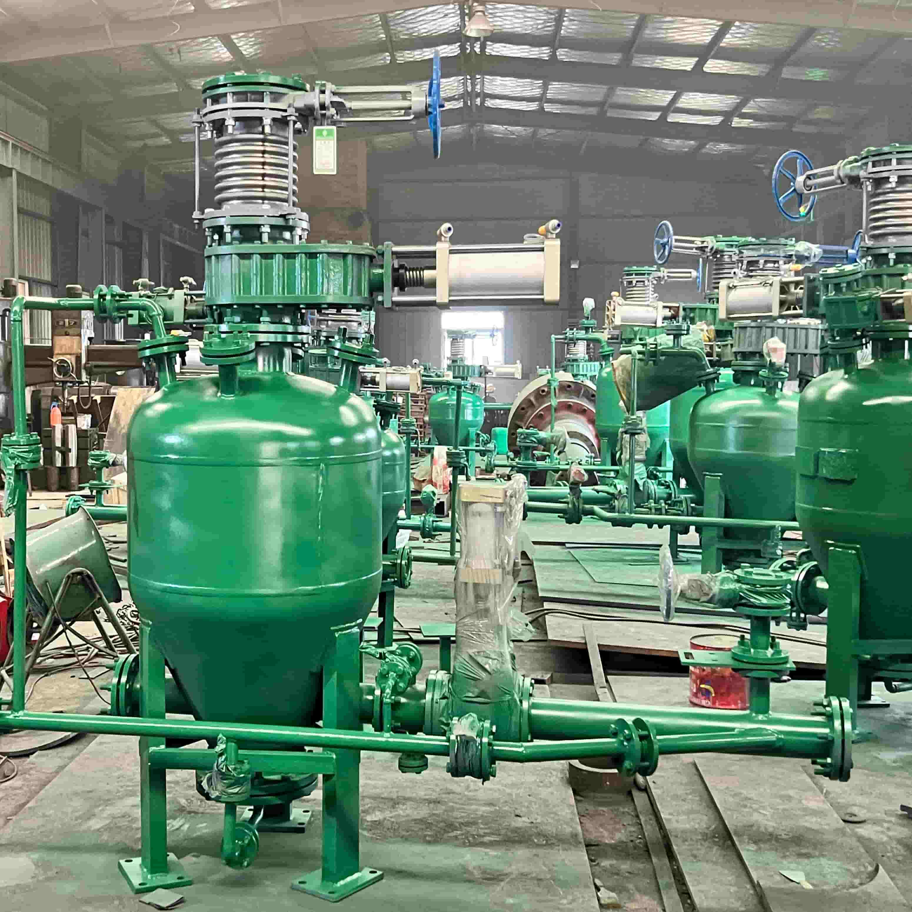
    What Is a PCD Dense Phase Pneumatic Conveying Vessel Pump? PCD‑type Positive‑pressure Dense‑phase Pneumatic Conveying Pressure Vessel Pump With years of R&D and abundant practical field experience, our company has developed pneumatic conveying equipment and complete process systems with independent intellectual property rights. Its key performance indicators have reached internationally advanced levels. The volume of each pump is custom‑designed according to material properties, particle size, conveying distance and conveying capacity. This customized single‑unit design minimizes conveying energy consumption while fully meeting process requirements. Based on parameters provided by customers, including powder material specifications & properties, conveying distance, throughput and site geographical conditions, we formulate the optimal overall solution for pneumatic conveying, covering air volume calculation, pipeline configuration, dust collection for receiving silos, and after‑sales service planning.  Working Principle of Dense‑Phase Vessel Pump Dense‑phase vessel pumps perform intermittent batch conveying in four core stages. During the filling stage, bulk material drops into the pressure vessel by gravity through the inlet valve. Excess air is discharged to dust‑collection equipment to guarantee efficient filling. Next comes pressurization: inlet and vent valves seal off. Compressed air charges the vessel, reaching working pressures of 7 Barg and higher. For conveying, the discharge valve activates. Compressed air drives powders along piping under dense‑phase conditions. Flow patterns shift between fluidized moving bed and slug‑plug flow, which depends entirely on material physical properties. Finally, purging takes place as system pressure falls. Remaining air cleans out pipeline interiors and mitigates clogging risks. Improved structural designs realize semi‑continuous production: vessel refilling occurs without pipeline depressurization or flow interruption. Dual‑vessel layouts are widely adopted to realize almost continuous material delivery. -- Application Fields PCD‑series pneumatic conveying equipment and systems are widely adopted in building materials, chemical, mining, power, and metallurgy industries. Typical conveyed materials: cement, raw meal, fly ash, slaked lime, dry‑disposed carbide slag, slag powder, steel slag powder, coal powder, alumina powder, vanadium ore powder, phosphorus powder, pyrophyllite powder, silicone powder, etc. Why Choose Dense Phase Over Dilute Phase? 1. Energy Efficiency Dense phase systems use significantly less compressed air per ton of material conveyed—often one-third the air consumption of dilute phase systems . This directly reduces your operating costs. 2. Reduced Wear & Maintenance Because the material moves at low velocity, pipe and elbow wear is dramatically reduced . Some systems incorporate pocket elbows that trap material to protect the deflection point—extending elbow life up to 10:1 compared to standard designs . 3. Material Integrity Friable or fragile products (like coated urea, extruded alumina, or food ingredients) arrive intact with minimal breakage . 4. Fewer Moving Parts Many modern dense phase pumps use only one moving part—a dome valve or cone valve on the inlet—reducing maintenance downtime and spare parts inventory  Choosing the Right Dense Phase Vessel Pump When selecting a system, consider: Material characteristics – Bulk density, particle size, abrasiveness, friability, and whether the material is fluidizable  Conveying distance – Standard systems handle up to 200 meters; high-capacity models extend to 1,000–1,500 meters  Throughput requirements – From small batch systems at 0.1 t/h to high-tonnage systems over 250 t/h  Temperature requirements – Some designs operate at up to 480°C  Pressure vessel codes – Vessels can be manufactured to most international codes (ASME, PED, etc.)    The Bottom Line The dense phase pneumatic conveying vessel pump remains the go-to solution for industries that demand reliable, energy-efficient, and low-maintenance bulk material handling. Whether you're moving cement across a plant, conveying fly ash from a power station, or handling abrasive minerals, this proven technology delivers long-distance capability, material integrity, and lower cost of ownership . Looking to upgrade or specify a new system? Contact our team with your material properties and capacity requirements for a customized solution.
  • What Size Vertical Roller Mill Do You Need? A Complete Sizing Guide
    What Size Vertical Roller Mill Do You Need? A Complete Sizing Guide
    Sep 03, 2026
    Choosing the right size vertical roller mill is one of the most important decisions when setting up a calcite powder processing plant. An undersized mill will fail to meet production targets, while an oversized mill wastes capital and energy. This guide walks you through the key factors to consider when selecting the correct vertical roller mill size for your operation. Why Mill Sizing Matters A vertical roller mill is a long-term investment. The right size ensures: Stable and continuous production Lower energy consumption per ton Extended equipment service life Better return on investment Selecting the wrong size can lead to frequent shutdowns, high wear rates, and increased operating costs. Key Factors That Determine Vertical Roller Mill Size 1. Required Production Capacity The very first factor to clarify is your target hourly throughput in tons. For calcite‑grinding vertical roller mills, production capacity generally falls within 5‑50+ tons per hour. Defining your daily or monthly output goals early on allows you to shortlist suitable mill models efficiently. Capacity Range (t/h) Typical Application 5–10 Small-scale powder plants 10–20 Medium-sized processing lines 20–30 Large industrial operations 30–50+ High-volume GCC production bases   2. Target Product Fineness Your desired finished‑powder fineness is a critical parameter influencing vertical roller mill selection. Finer powders demand higher grinding energy input, which will lower your overall production throughput.   - 200‑325 mesh – Coarse powders, widely used for building materials and industrial fillers - 400‑800 mesh – Medium‑fine powders, ideal for paper, rubber and plastic industries - 800‑1250 mesh – Ultra‑fine powders, engineered for premium‑grade coatings, paints and special‑purpose applications   To maintain the same hourly output when producing 1250‑mesh ultra‑fine powder, you may have to upgrade to a larger‑capacity model or opt for a vertical roller mill custom‑built for ultra‑fine grinding.   3. Raw Material Characteristics Calcite ore differs significantly from one deposit to another, which must be factored into your mill‑selection decision. Key material‑related parameters include: Feed Particle Size – Raw feed with larger particle dimensions calls for a vertical roller mill fitted with an adequate grinding‑table diameter and optimized roller geometry. Moisture Level – Calcite containing high moisture demands a mill equipped with built‑in drying functions. Hardness and Abrasive Properties – Pure calcite is comparatively soft at Mohs hardness 3; however, mineral impurities can accelerate component wear and alter your equipment‑sizing requirements. A vertical roller mill capable of delivering 10 t/h throughput for dry, high‑purity calcite is unlikely to maintain that same production rate when processing wet or impurity‑laden feedstock.   4. Energy Consumption & Operating Cost Thanks to economies of scale, larger‑size mills usually deliver a lower per‑ton power consumption. Yet this advantage only applies when the equipment runs close to its rated capacity. Buying a 20 t/h mill for an actual demand of just 6 t/h will lead to unnecessary power waste from under‑loaded operation. It is recommended to align mill capacity with your real‑world output requirement, while reserving a reasonable 10‑20 % spare margin for future production expansion.   5. Plant Layout & Available Space While vertical roller mills boast a more compact footprint than ball mills, large‑capacity units still demand substantial headroom and floor area on‑site.   Verify the following site conditions in advance: - Clear workshop height reserved for mill installation - Sufficient layout space for classifier, cyclone collector, baghouse filter and conveying systems - Unobstructed maintenance access surrounding the grinding table and rollers 6. Budget & Return on Investment   High‑capacity mills carry a higher initial capital outlay, yet they can bring superior long‑term economic benefits when your production volume can support the investment. Take these expenses into your financial evaluation: - Up‑front equipment purchase cost - Installation and commissioning charges - Per‑ton energy‑consumption expense - Replacement cycle of wear‑resistant components - Labor and routine maintenance expenditure For most medium‑sized calcite processing plants, a mid‑capacity mill operated at 80‑90% load rate usually yields the optimal return on investment. Step-by-Step Sizing Process Follow these steps to determine the right vertical roller mill size: Define your target output – Required tons per hour or tons per year. Specify powder fineness – Target mesh size and particle size distribution. Analyze raw material – Feed size, moisture, and impurity content. Evaluate plant conditions – Available space, power supply, and environmental requirements. Consult manufacturer – Provide your data and request a technical proposal with specific model recommendations. Compare options – Evaluate capacity, energy consumption, price, and after-sales support. Conclusion Choosing the right size vertical roller mill is a balance between production demands, powder specifications, and budget. A professional manufacturer can help you determine the optimal model based on your specific calcite processing requirements. For a customized sizing recommendation and factory quotation, contact us with your capacity target and fineness requirement — our engineering team will provide a tailored solution within 24 hours.  
  • Vertical Roller Mill vs Ball Mill: Which Is Better for Your Grinding Plant?
    Vertical Roller Mill vs Ball Mill: Which Is Better for Your Grinding Plant?
    Aug 28, 2026
    1. Equipment structure analysis 1. Ball Mill  The ball mill is composed of a horizontal cylinder, a hollow shaft for feeding and discharging materials, and a grinding head. The cylinder is a long cylinder with a grinding body inside. Generally, it is a steel ball, and it is loaded into the cylinder according to different diameters and certain proportions. The grinding body can also be made of steel segments. Figure 1: Structural schematic diagram of ball mill The material is selected according to the particle size of the grinding material, and the material is loaded into the cylinder through the hollow shaft at the feed end of the ball mill. When the ball mill is rotated, the grinding body is attached to the lining plate of the nearby cylinder due to the action of inertia, centrifugal force and friction. The cylinder is taken away, and when it is brought to a certain height, it is thrown down due to its own gravity, and the falling grinding body crushes the materials in the cylinder like a projectile. The material is spirally and evenly entered into the first chamber of the mill through the feeding hollow shaft by the feeding device. There are stepped lining boards or corrugated lining boards in the chamber, and steel balls of different specifications are installed inside. The rotation of the cylinder produces centrifugal force to bring the steel balls to a certain height. After falling down, it will hit and grind the material. Materials get coarse grind in the first warehouse, then into the second warehouse through the single-compartment. The second warehouse has flat liner and also filled with balls , then grind the material again. The powder is discharged through the discharge grate to complete the grinding operation.During the rotation of the cylinder, the grinding body also has a phenomenon of slipping. During the sliding process, the material is given a grinding effect. In order to effectively use the grinding effect, when grinding the material with a larger particle size of generally 20 mesh, the grinding body cylinder Divided into two sections by partition board, it becomes a double warehouse. When the material enters the first warehouse, it is crushed by steel balls. When the material enters the second warehouse, the steel forging grinds the material, and the finely ground material is hollowed out from the discharge end. Shaft discharge, when grinding materials with small feed particles, such as sand No. 2 slag, coarse fly ash, the mill cylinder can be a single-silo mill without partitions, and the grinding volume can also be used for steel sections . 2. Vertical Mill Vertical mill is an ideal large-scale grinding equipment, widely used in cement, electric power, metallurgy, chemical industry, non-metallic minerals and other industries. It integrates crushing, drying, grinding, grading and conveying, and has high production efficiency. It can grind block, granular and powder raw materials into required powder materials. Figure 2: Schematic diagram of vertical mill structure The vertical mill works as follows: the motor drives the grinding disc to rotate via a reducer. Material is fed through an airlock feeder onto the center of the rotating disc, then moves outward by centrifugal force into the grinding zone. There, grinding rollers apply hydraulic pressure to crush and shear the material. (Vertical Roller Mill)   Hot air rises through a wind ring around the disc, blowing the ground material upward. Coarse particles fall back to the disc for regrinding, while the hot air simultaneously dries the material. Fine powder is carried into a separator for classification — qualified product exits with the airflow and is collected by a dust collector, while oversized particles return to the disc for further grinding. This cycle completes the entire grinding process. 3. Grinding mechanism of ball mill and vertical mill   3.1 Grinding mechanism of ball millAs we all know, as a traditional grinding equipment, the ball mill has always been in a monopoly position in the grinding operation of materials. Due to the following defects in the grinding mechanism of the ball mill, the effective utilization rate of energy is extremely low. According to data reports, generally only 1 to 3 %. Therefore, the energy saving of grinding operation is also one of the issues that should be paid attention to in energy saving and consumption reduction. The grinding mechanism of the ball mill is based on impact and grinding, and its characteristics: (1) It is necessary to bring dozens of tons, even hundreds of tons of grinding bodies and materials to a certain height at the same time; (2) The force of the grinding body acting on the material changes greatly, which cannot be controlled by humans; (3) There are useless collisions between the grinding bodies and between the grinding bodies and the liner, and a large amount of energy is wasted; (4) Over-grinding phenomenon exists; (5) Loud noise, generally 100-120dB (A sound level); (6) The grinding body consumes a lot. In the past, the energy-saving transformation of the grinding system was limited to the transformation of the ball mill itself and its system, such as improving the mill liner, compartment plate, adjusting the gradation of the grinding body, ventilation inside the mill, reducing the particle size of the incoming material, etc. Achieved a certain effect of increasing production and saving energy, but did not fundamentally solve the problems existing in the grinding mechanism of the ball mill.3.2 Grinding mechanism of vertical mill  When the vertical mill grinds materials, it squeezes the material bed formed by the loose materials through the surfaces of the two tightly pressed rolling elements inside, and gradually crushes or grinds them into powder. The grinding rollers in the vertical mill are movable, and the grinding pressure is transmitted by the compressed material bed filled in the gap between the rollers. Vertical mill operation has the following main features: (1) The force of the grinding roller on the material can be controlled artificially to ensure that the force on the material and equipment is uniform and constant. (2) Qualified fine powder can be sorted out in time. (3) The vertical mill body realizes low-noise operation. (4) Integrates five processes of crushing, grinding, drying, grading and conveying. Due to the reasonable structure and grinding method of the vertical mill, the grinding efficiency of the vertical mill is higher than that of the ball mill. 2、 Analysis of grinding system   1. Comparison of Ball Mill and Vertical Mill Pulverization Schemes 1.1 Comparison of Process Plans for Ball Mill Pulverization and Vertical Mill Pulverization Limestone grinding can be done using a vertical mill or ball mill. The top of the vertical mill comes with a separator. By adjusting the air ring valve, the product fineness can be changed, and the load of the material bed inside the mill can be uniform and stable. After the powder is discharged from the mill, it enters the pulse bag dust collector with the exhaust fan airflow for collection, and then enters the limestone powder silo for storage through horizontal and vertical conveying equipment, as shown in Figure 4. If it is a ball mill, after the powder is discharged, it first passes through an efficient powder concentrator for sorting. The powder concentrator has a rotor driven by a variable frequency motor and rotating vertically. By adjusting the speed of the rotor and the ventilation rate of the powder concentrator, the fineness of the finished product is adjusted. The sorted coarse material is sent back to the inlet of the mill through a screw conveyor for further grinding. The powder with the required fineness enters the pulse bag dust collector along with the exhaust fan airflow for collection, and then enters the limestone powder silo for storage through horizontal and vertical conveying equipment, as shown in Figure 3. Figure 3: Process Flow Diagram of Ball Mill Pulverizing System Figure 4: Process Flow Diagram of Vertical Grinding Powder System The process flow shown in Figure 3 is a "two-stage dust collection system". The process is complex, there are many system equipment, and there are many system failure points. The system is characterized by difficult operation, multiple constraints on process layout, and a large footprint. Although high concentration dust collectors are not required, the relative investment is also significant. The process flow shown in Figure 4 is a "primary dust collection system". It has the advantages of simple process flow, fewer system equipment, fewer system failure points, convenient system operation, flexible process layout, and no wear on the main fan impeller of the system. But it requires the configuration of a high concentration dust collector, which is relatively expensive. Through comparison, it can be found that the vertical grinding process is simple, occupies a small area and space. The vertical grinding itself has a powder concentrator, and does not require additional powder concentrators and lifting equipment, resulting in fewer system equipment. The system has few fault points, convenient operation, and flexible process layout. The process is simple, the layout is compact, and can be arranged outdoors. The building area is about 70% of the ball mill system, and the building space is about 50-60% of the ball mill pulverizing system. 1.2 Comparison of Ball Mill Pulverizing and Vertical Mill Pulverizing System Schemes  The HVM type vertical mill pulverizing system used in a Fossil fuel power station is compared with the original ball mill pulverizing system of the plant. Table 1: Comparison of Limestone Powder Preparation System Schemes From Table 1, it can be seen that using a ball mill milling system incurs nearly 10% more investment than using a vertical milling system. However, all technical and economic indicators are lower than those of the vertical grinding powder system. Especially for the power consumption per unit product, the vertical milling system is 30% to 40% lower than the ball milling system. It can be seen that the vertical grinding powder system is far superior to the ball mill powder system in terms of technical and economic indicators. In terms of other technical indicators, the vertical grinding powder system is also much more advanced. 3、 Conclusion analysis Compared with ball mill systems, vertical mill systems have the following advantages: 1. Lower investment cost Simple process, compact layout and small‑footprint design. With an integrated powder separator, no extra separators or lifting equipment are required. Its floor area is around 70% and occupied space 50‑60% of that of a ball‑mill system. 2. High efficiency, energy‑saving & eco‑friendly Adopting material‑bed grinding, it cuts power consumption by 30‑40% versus ball mills, with higher energy savings for high‑moisture materials. Noise is reduced by 20‑25 dB; the fully‑sealed negative‑pressure operation achieves zero dust emission. 3. Convenient operation & maintenance Automatic control system supports remote operation. Quick replacement of roller sleeves and liners via cylinder maintenance and rocker‑arm turnover reduces downtime. Longer service life of wear‑resistant parts lowers replacement frequency. 4. Stable product quality & fast adjustment Residence time of materials inside the mill is only 2‑3 minutes (15‑20 minutes for ball mills). This enables rapid testing and adjustment of chemical composition and fineness, delivering products with stable components and uniform particle‑size distribution. 5. Low wear loss & high utilization of grinding parts No direct metal‑to‑metal contact between grinding rollers and disc results in minimal abrasion. Metal consumption stands at 5‑10 g/t of finished product, and wear‑resistant components can serve for about 10,000 hours. 6. Strong drying capacity Hot air is used for material conveying. By adjusting inlet air temperature, materials with moisture content up to 20% can be dried.  

  • Why Bentonite Producers Are Switching to Vertical Roller Mills
    Why Bentonite Producers Are Switching to Vertical Roller Mills
    Jul 27, 2026
    Bentonite is a versatile mineral used in drilling fluids, foundry sand binders, iron ore pelletizing, and even cosmetics. But processing it efficiently has always been a challenge—especially when using traditional equipment like Raymond mills or ball mills. Here’s why more bentonite producers are making the switch to vertical roller mills.   The Problem with Traditional Mills Bentonite raw ore often comes with high moisture content (15–35%) and requires fine grinding—typically 200 mesh or finer. Raymond mills struggle with these conditions. They suffer from: Low single-machine output High wear and maintenance costs Dust leakage and poor working conditions Low automation levels   For large-scale producers, these limitations directly impact profitability. pic: Frame of Raymond Mill   The HCHVM Vertical Roller Mill Advantage Vertical roller mills address all these pain points. 1. Integrated Drying and Grinding Bentonite's high moisture is no longer a bottleneck. VRMs introduce hot gas directly into the grinding chamber, simultaneously drying and grinding the material in one step. This eliminates the need for a separate pre-dryer—saving both equipment costs and floor space.   2. Higher Efficiency & Lower Power Expense Adopting material bed extrusion grinding,industrial slag grinding vertical roller mill are far more energy-saving than impact-type ball mills, delivering 30%–50% power reduction. Practical application data proves bentonite manufacturers can slash power expenditure by 3.3$ per ton with VRMs.   3. HFVRM Precise Fineness Control Bentonite applications demand consistent particle size—whether it's 200 mesh for drilling mud or 1500 mesh for high-end coatings. Modern VRMs are equipped with dynamic classifiers that allow real-time fineness adjustment without stopping production. Output ranges typically span 100–2500 mesh depending on the model.   4. Lower Wear and Maintenance The grinding bed itself provides a cushioning effect, reducing direct contact wear between rollers and the grinding table. Wear parts are made from high-chromium or composite alloys, delivering extended service life—2–5 years for non-metallic mineral applications.   5. Cleaner, Quieter Operation HFVRM VRMs operate under negative pressure with pulse-jet dust collectors, keeping emissions below strict environmental standards. Noise levels are also significantly lower than traditional mills—roughly 15 dB quieter than Raymond mills.   Real-World Results Data from operating bentonite VRM lines confirms the benefits: One plant producing 325-mesh bentonite achieved daily output exceeding 300 tons, with monthly electricity savings of nearly USD 8000. A 200-mesh bentonite line with 98% passing rate achieved 35% lower energy consumption than a traditional Raymond mill setup.   Annual production capacity for a single VRM line can exceed 150,000 tons. For bentonite producers looking to scale up, reduce operating costs, and meet stricter environmental standards, vertical roller mills are no longer a luxury—they're a competitive necessity. The technology has matured, proven itself in real-world applications, and is increasingly the go-to choice for new and expanded bentonite processing lines. Interested in upgrading your bentonite grinding line? Contact us for a customized solution and feasibility analysis.   Contact Us or through the WhatsApp      
  • The Smart Choice for Calcite Ultrafine Milling: How Vertical Roller Mills Deliver Higher Value for You?
    The Smart Choice for Calcite Ultrafine Milling: How Vertical Roller Mills Deliver Higher Value for You?
    Jul 20, 2026
    Calcite is a natural calcium carbonate mineral and one of the most widely used and highest-consumption non-metallic mineral raw materials in the industrial sector. Processed Ground Calcium Carbonate (GCC) powder plays an irreplaceable role in numerous industries including plastics, coatings, papermaking, rubber, construction materials and daily chemical products.   Nevertheless, processing raw calcite ore into ultrafine powder that meets stringent downstream specifications (such as 325 mesh, 800 mesh and even above 1250 mesh) is no simple task. When used for high-fineness grinding, traditional ball mills and Raymond mills commonly suffer from high energy consumption, poor particle size distribution control and rapid equipment wear. For enterprises committed to developing the non-metallic mineral grinding business, what solution stands out as the most competitive option available today? The answer is increasingly clear: Vertical Roller Mill (VRM). This article analyzes the core advantages of the HVM vertical roller mill in calcite processing, and explains how precise technical selection helps enterprises stand out in fierce market competition.   Why is the HVM Vertical Roller Mill an Ideal Choice for Calcite Processing? Compared with traditional grinding equipment, heavy-duty vertical roller mills deliver revolutionary technological upgrades in calcite processing, with prominent advantages reflected in the following core aspects: 1. Energy Saving and Consumption Reduction, Solving Core Cost Pain Points The HVM vertical roller mill adopts the bed grinding principle. Materials are crushed and ground through extrusion between the grinding disc and grinding rollers, achieving a far higher energy utilization rate than the impact grinding mode of ball mills. Mass field applications prove that the system power consumption for calcite processing by vertical roller mills can be reduced by 30%-50% compared with traditional ball mills. Against the backdrop of continuously rising energy costs, this advantage directly translates into substantial profit margins for enterprises.   2. Precise Powder Control to Meet High-end Market Requirements Equipped with a high-efficiency dynamic classifier, the HVM vertical roller mill enables real-time adjustment of finished product fineness and achieves a narrow particle size distribution. Whether producing 325-mesh conventional filler powder or high-value-added 800-mesh and 1250-mesh ultrafine powder, operators can realize accurate fineness control simply by adjusting the classifier speed. This ensures stable product indicators and fully meets the stringent standards of high-end customers.   3. Integrated Process Design to Simplify Production Line Layout A single HVM vertical roller mill integrates five core functions: crushing, grinding, classifying, drying and conveying. For calcite raw materials with a certain moisture content, drying and grinding can be completed synchronously inside the mill. This greatly simplifies the production process, reduces investment in auxiliary equipment, and saves plant floor space.   Tap into High-value Calcite Markets The selection of appropriate processing equipment directly determines your access to high-margin end markets. Conventional Filler Market (200–400 mesh): Featuring high output and steady demand, this segment forms the fundamental market for vertical roller mills. For instance, the HVM1900 vertical mill boasts a production capacity of 23 to 68 tons per hour, fully capable of supporting large-scale industrial production.   High-value-added Ultrafine Powder Market (600–2500 mesh): This is the core driver of profit growth. Ultrafine calcium carbonate powder commands premium prices for applications in high-end coatings, sealants, automotive paints and other sectors. To cater to such demands, professional ultrafine vertical mills (the HVM series, for example) can control product particle size at D97 = 5–30 microns, empowering manufacturers to capture greater share in high-end markets.   Key Considerations for Equipment Selection For domestic machinery manufacturers striving to make breakthroughs in overseas markets, merely supplying equipment parameters is insufficient. It is equally critical to demonstrate in-depth understanding of application processes. The following factors should be prioritized when proposing solutions to clients:   Raw Material Compatibility Calcite features low hardness (Mohs hardness 3), yet finished products demand stringent whiteness and purity standards. The equipment must adopt a low-wear structural design to prevent product contamination caused by abrasion of grinding rollers and grinding discs during milling.   Intelligent Control System Modern vertical roller mills shall be equipped with PLC automatic control systems to support one-click start-stop, remote monitoring and fault diagnosis. This functionality drastically cuts labor costs and technical barriers for overseas customers.   Environmental Compliance Negative-pressure operation and high-efficiency pulse dust collectors are standard configurations. Ensuring dust emission concentration below 20 mg/Nm³ is a prerequisite to comply with increasingly stringent global environmental regulations.     In the non-metallic mineral processing industry, shifting focus from "selling standalone equipment" to "providing comprehensive processing solutions" holds the key to capturing overseas markets. When it comes to calcite grinding, vertical roller mills stand out as the optimal solution to help clients cut costs, boost efficiency and upgrade product quality, thanks to their three core strengths: outstanding energy efficiency, precise particle size control and highly integrated system design.   If you wish to learn more detailed information about the HVM Vertical Roller Mill, please click:www.hengchengmill.com  or Contact Us!  
  • One Verical Roller Mill, Multiple Minerals: How to Maximize Your Toll Grinding Business in the Middle East?
    One Verical Roller Mill, Multiple Minerals: How to Maximize Your Toll Grinding Business in the Middle East?
    Jul 08, 2026
    Within the rapidly evolving industrial landscape of the Middle East, toll grinding — processing raw materials into powder for a processing fee — has emerged as a stable and profitable business model. From the Eastern Province of Saudi Arabia to industrial zones across the UAE, small and medium-sized processing enterprises enjoy steady demand for mineral powders stemming from oil drilling, construction and manufacturing sectors. Yet every OEM grinder faces a challenge: demand for a single mineral can be seasonal and volatile. Orders for bentonite used in drilling muds surge amid active oil operations before tapering off. Demand for calcium carbonate fluctuates in line with construction cycles. So how can you keep your grinding plant operating at full capacity all year round? The solution: Invest in equipment capable of processing multiple minerals, not just one. The Drawbacks of Single-Mineral Grinding Mills Traditional bentonite grinding equipment, especially outdated Raymond Mills and Ball Mills, are generally designed and calibrated for one specific raw material only. Switching to a different mineral brings the following headaches: Complicated adjustments: You have to modify grinding parameters and classifier settings, and sometimes even replace internal wear parts. Lengthy downtime: Recalibration between different batches can take hours or even days. Risk of cross-contamination: Residues from the previous mineral mix into the next batch of material.
1 2

Want to talk? Reach out to our experts

Contact Us

leave a message

leave a message
If you are interested in our products and want to know more details,please leave a message here,we will reply you as soon as we can.
submit
Contact us:margo@hfvrm.com

Home

Products

WhatsApp

contact